Most beam saws and CNC machines support DXF file imports, and MaxCut can export your optimisation layouts directly to this format. If your machine has a DXF import option, you can use MaxCut's Export Layouts tool to send your cut data across.
To export an optimisation layout to DXF:
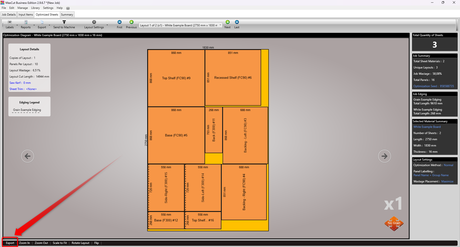
Optimise the job you would like to export so your optimisation layout is visible.
Go to File > Export > Optimisation Layouts on the menu bar. Alternatively, select the Export button at the bottom left corner of the Optimisation Screen. You can also use the Send to Machine button, which opens the same DXF export options directly.
Select DXF as your file format.
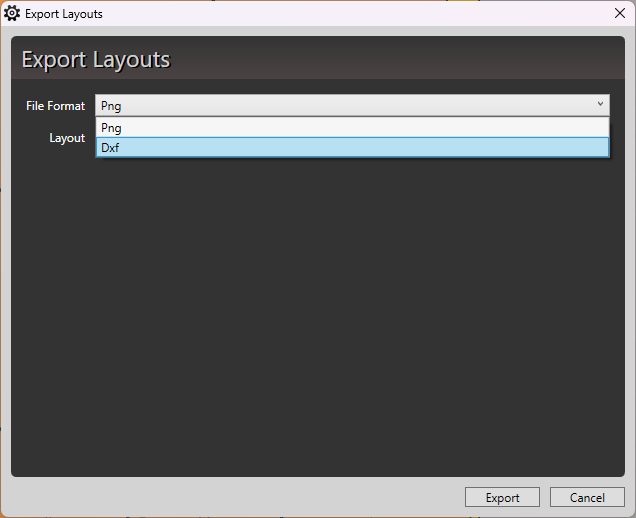
Choose whether to export the current sheet layout or all layouts for the job.
Configuring Your DXF Export Settings
From version 2.9.6.7, MaxCut includes a DXF Export Settings dialog that gives you control over which layers are included and how they are named and coloured.
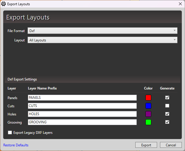
MaxCut exports four layer types by default: Panels, Cuts, Holes, and Grooving. Each has a Generate checkbox next to it. Checking all boxes means all four layer types will be included in the export. Unchecking any box will exclude that layer from the exported file.
The default layer naming conventions and colours are:
Panels: named PANELS, shown in red
Cuts: named CUTS (with width appended, e.g. CUTS_16), shown in blue
Holes: named HOLES (with diameter and depth appended, e.g. HOLES_20_D10), shown in purple
Grooving: named GROOVING (with width and depth appended, e.g. GROOVING_30_D15), shown in green
You can customise both the layer name prefix and the colour for each layer. This is useful when your CAM software assigns machining operations based on layer names or colours. For example, you could rename HOLES to DRILL if that is what your machine expects. Note that the layer name acts as a prefix, so individual variations within that layer type remain distinct (e.g. HOLES_20_D10 and HOLES_20_D15 will appear as separate layers).
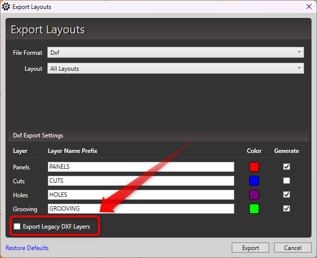
Export Legacy DXF Layers
If you have already built a workflow around the DXF export format used in earlier versions of MaxCut, you can check the Export Legacy DXF Layers option. This preserves the previous layer structure and naming, so your existing automations or CAM configurations will continue to work without changes.
Exporting
Once your settings are configured, click Export.
You will be prompted to choose where to save the exported file. Select an appropriate folder and click OK.
MaxCut will display a confirmation message when the export is complete.
On Your CNC or Beam Saw
Open your machine's controller application and locate the DXF import option. For example, on a Biesse machine this would be BiesseWorks.
Select the DXF file you exported from MaxCut.
Map each DXF layer to the appropriate tool or operation in your controller.
If Your Machine Requires Something Different
Every machine and CAM setup is a little different. If your machine requires a specific file format or layer configuration that MaxCut doesn't currently support, we'd love to hear about it.
You can fill out our Send to Machine form at https://maxcutsoftware.com/send-to-machine/ to share details about your machine and integration needs, or reach out to us directly at support@maxcutsoftware.com.
This helps us understand how you are using MaxCut and guides future CNC integration development.